

tcfengineering
-
Innehålls Antal
36 -
Gick med
-
Besökte senast
-
Dagar Vunna
7
Innehållstyp
Profiler
Articles
Media Demo
Forum
Bloggar
Kalender
Galleri
Filer
Butiken
Allt postat av tcfengineering
-
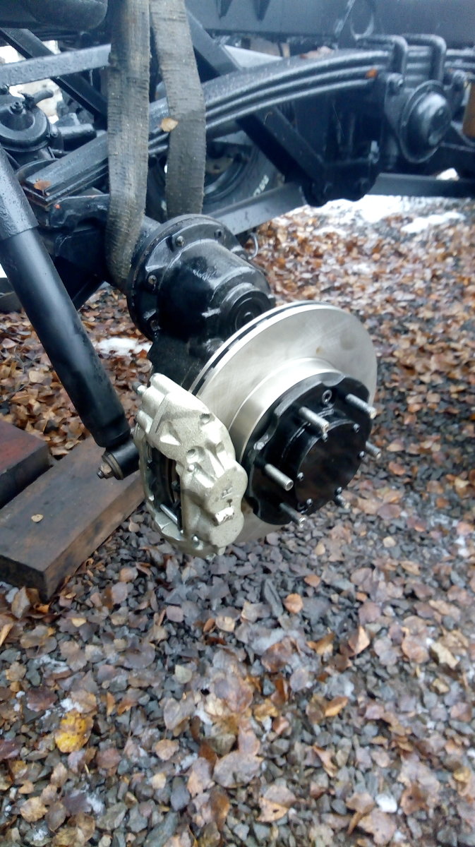
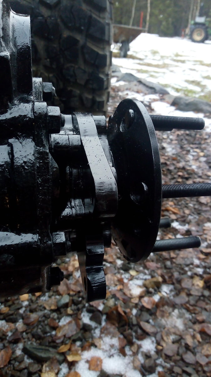
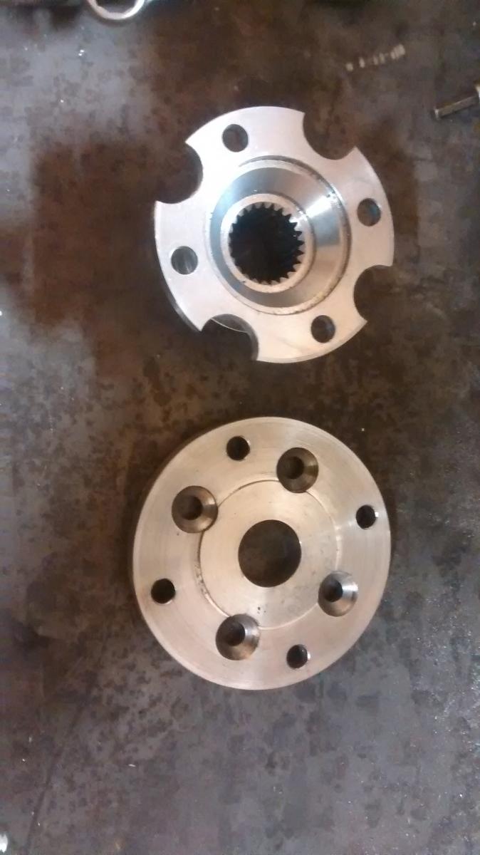
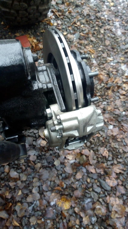
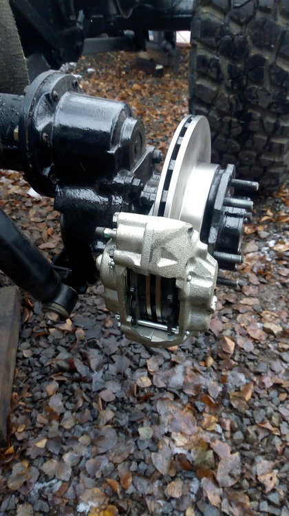
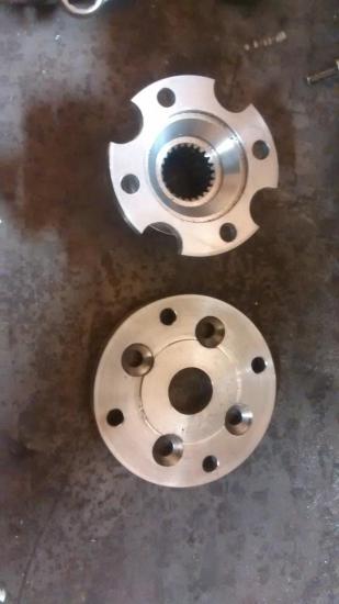
The piece on the outside of the brake disc is the old toyota hub with quite a lot of material taken off it. This is really just a glorified wheel spacer which gives clearance for the wheel, but it also makes everything hub centric ie. it centres the wheel so it doesnt just rely on the wheel studs. The original Volvo hub is centred on the inside of the brake disc, then the toyota hub is centred on the internal diameter of the brake disc. The toyota and volvo hubs are bolted together.
- 42 svar
-
- 6
-

-

-
Some more
- 42 svar
-
- 8
-
-
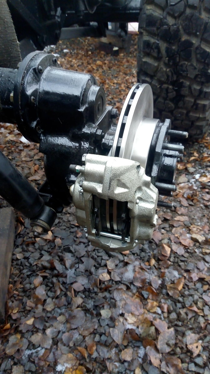
Hello, its a long time since I posted anything, but I have been busy ! Disc brakes - that should be easy, right ....... !?! Ha ha, totally not easy, I have put so many hours into this, I cant even explain it. My aim with the disc conversion was the following : I wanted to use matched discs and calipers from the same vehicle preferably a big 4x4 I didnt want any modifications to the discs or calipers, so I can service in the field with standard parts I wanted standard wheels to fit so if I damage one I can get home I wanted the brackets to fit to the same place the original Volvo brakes attach I wanted to replace the outer oil seal that is really hard to get with a standard off the shelf one. I think I have achieved all of this, the only compromises are : You have to split the caliper to change the brake disc, or strip the portal hub to tighten the bearings I have modified wheels to keep the vehicle width down. Standard Toyota 6 stud wheels fit and you could use them to get you home no problems, but I have moved the centres out on my set. Overall width has increased by 23mm so thats not too bad. All in all very happy, just have to make new pipes and bleed them and then I can test them out. Now for some pics


- 42 svar
-
- 7
-
-
-
Hello, yes there are quite a few updates to this project. Its slow going, but the cab is back on, and the disc conversion is done. I am part way through wiring, and then I am ready for a little test drive and see how it works. I am away now, but when I get back I will take some pics and post them up here.
- 42 svar
-
- 8
-
-
Hej, I am working on my own brake conversion now for my 1314. I dont want to change anything on the original parts apart from drill 5 holes in the original hub and skim the surface less than 1mm to mount the brake disc. In order to achieve this, you need to use a very large brake disc and this means that my solution wont work with the original wheels. This is OK for me as I have changed to 17" wheels in order to get a better choice of tyres. I am using a Landrover Discovery 4 rear disc and brake caliper. The disc is 350mm diameter and I will use rear calipers all round (2 per wheel on the front, 1 per wheel on the back). Time will tell if this is a good solution, but I think it will be good. I dont know if I will have to change the brake master cylinder yet. Based on my experience so far, I think that it would have to be a very expensive kit to make commercial sense. There is a lot work involved to get it right. When I get a bit further with it, I will post up some more info and pics on my engine conversion thread (Probably in a few months - I am not in a rush !)
- 13 svar
-
- 6
-
-
Thanks for your help. I have ordered the valves, I will update this thread when I fit them with some pictures.
- 16 svar
-
- 4
-
-
http://www.ebay.co.uk/itm/1-4-DC-12V-3way-2-position-Pneumatic-Electric-Solenoid-Valve-BSP-Air-Aluminum-/121880914346?hash=item1c60ab29aa:g:IiYAAOSwzhVWreBY The schematic on this one looks like the one on your post ? Thanks for your help
-
http://www.ebay.co.uk/itm/3-Way-2-Position-Pneumatic-Solenoid-Valve-PT1-8-Port-AC220V-110V-DC24V-12V-Y5G5-/222273307066?var=&hash=item33c08581ba:m:m-72hgsUgUGCume-mxAI79g What about this one ? Any better ? Thanks
-
What about this, would this work ? http://www.ebay.co.uk/itm/2-Way-NBR-Electric-Solenoid-Valve-Water-Air-N-O-12V-DC-1-4-Normally-Open-Type-/271888344686?hash=item3f4dcee66e:g:wvEAAOSwbsBXi0PV
-
Can anyone help me with some suggestions for a nice 12V valve setup to operate the vacuum for the difflocks on a TGB1314 ? I want to buy something new so that it is reliable. Any help would be greatly appreciated
-
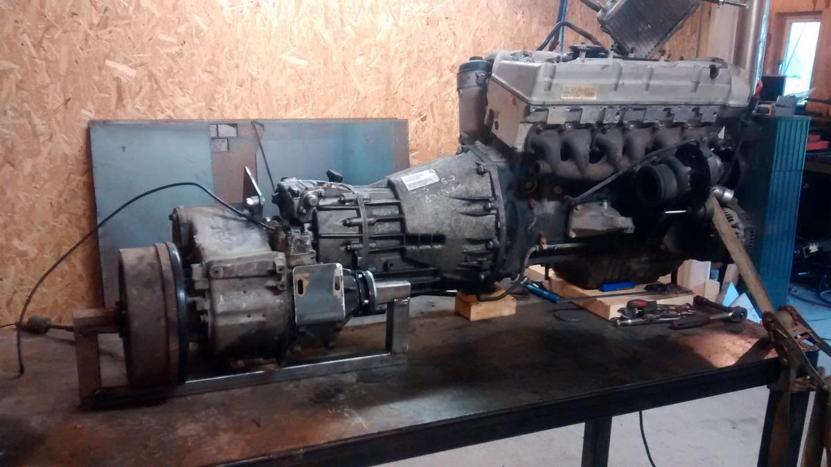
The disc conversion is only in my head right now ! I will put the standard brakes back on for besiktning and registering, and then work on that over the winter. I will put it up here as I progress with it. If it is any good, I am happy to share it with people. I just like these mercedes OM606/605 engines. They are very reliable, lots of potential for more power if you want it, they sound nice, a little bit more modern, hopefully better on diesel, etc .... The toyota swap would be a much simpler swap. This toyota engine and gearbox I have here would go straight in with not too many problems. The transfer box is all offset the right way. The only thing it doesnt have is a transmission handbrake, but that is easy to sort, in fact I think you can buy one off the shelf in Australia. I will take some more pics next week as the cab goes on. I am putting completely new wiring in, so this will take me a while as I am not too good with electrics.
- 42 svar
-
- 2
-
-
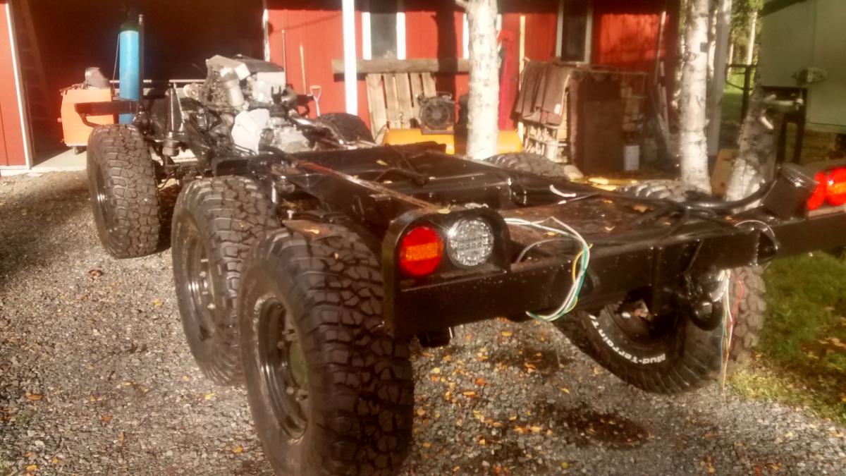
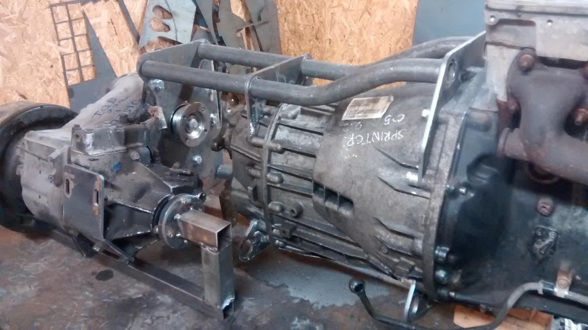
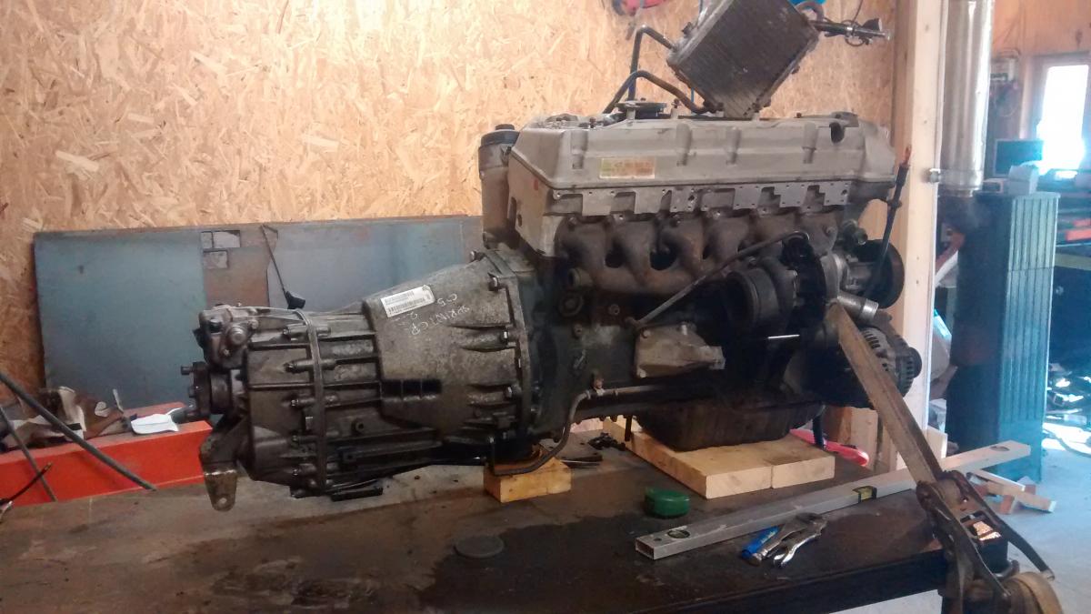
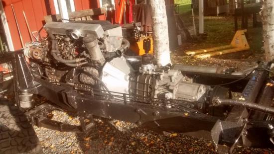
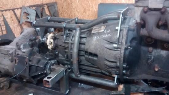
Hello, its been a long time coming, but here is an update ! This project has changed quite a bit. I am now using a landrover R380 gearbox with a short bellhousing from a Rover car. This joins onto the OM606 with a plate from SMT. I have the 0.73 5th gear in the gearbox and 1.003 ratio in the transfer box, so I think that it will be very nice cruising with 37" tryes. It is a very short gearbox/transfer box, so it works well in the chassis. If I was starting again, I think I would take the OM605 engine as it will make plenty of power and would give you a lot more room for everything, but I had a nice OM606 with low kms, so that is what I used. I moved the tubular cross member back about 15cms and I made a bolt in cross member which goes underneath the gearbox with the gearbox mounts. I took out 6cm from the rear propshaft and I have modified the sump on the engine to avoid hitting the axle. It has taken a long time because I stripped the whole chassis down and painted everything before building up. I always end up doing this with my projects, I start by thinking "I will just clean it and put some paint on it" and then I think "Oh well if I am doing this I might as well do it properly and take some parts off" Then suddenly, I have taken the whole vehicle apart into hundreds of pieces and I end up doing a full restoration. At least it is done properly I have nearly finished a lot of little jobs on the engine, and then I am also painting the cabin ready to go back on next week. I built my own 17" wheels and I have 37x12.50x17 BFG tyres, should be nice. I will also make my own disc brake conversion in the winter. I already have the calipers, and I think I may have found a disc which works. It will keep the original bolt pattern for the wheels. The Mercedes gearbox and frame/coupling to LT230 are for sale if anyone is interested, I also have a 4.0l toyota engine and gearbox here which could be used for a conversion, that is for sale too.


- 42 svar
-
- 12
-
-
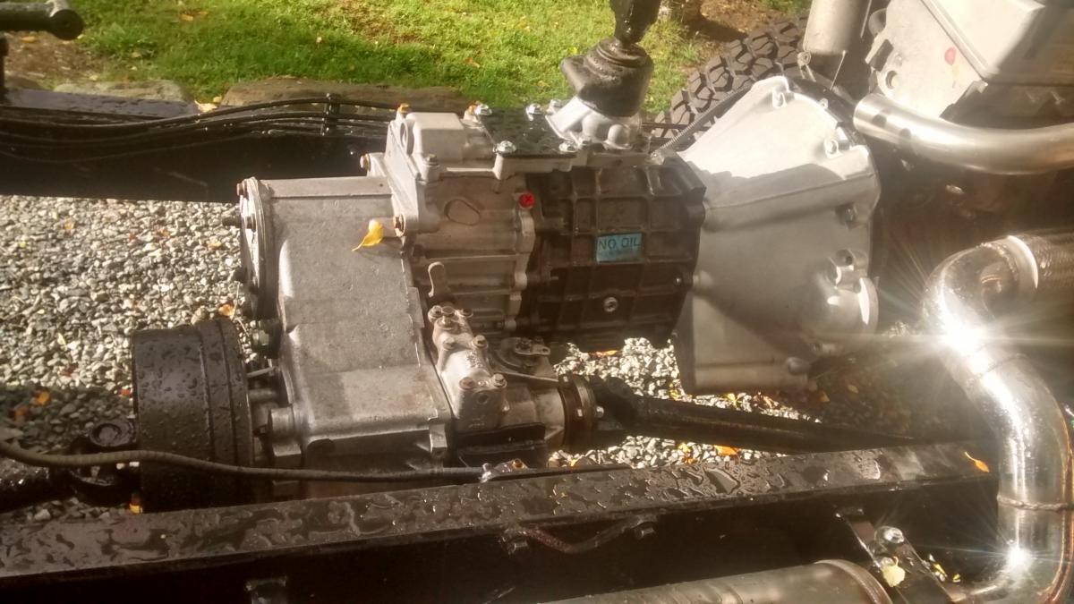
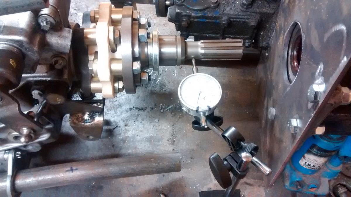
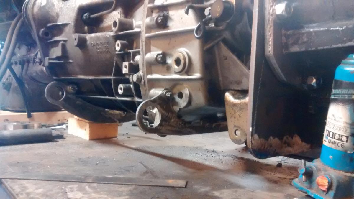
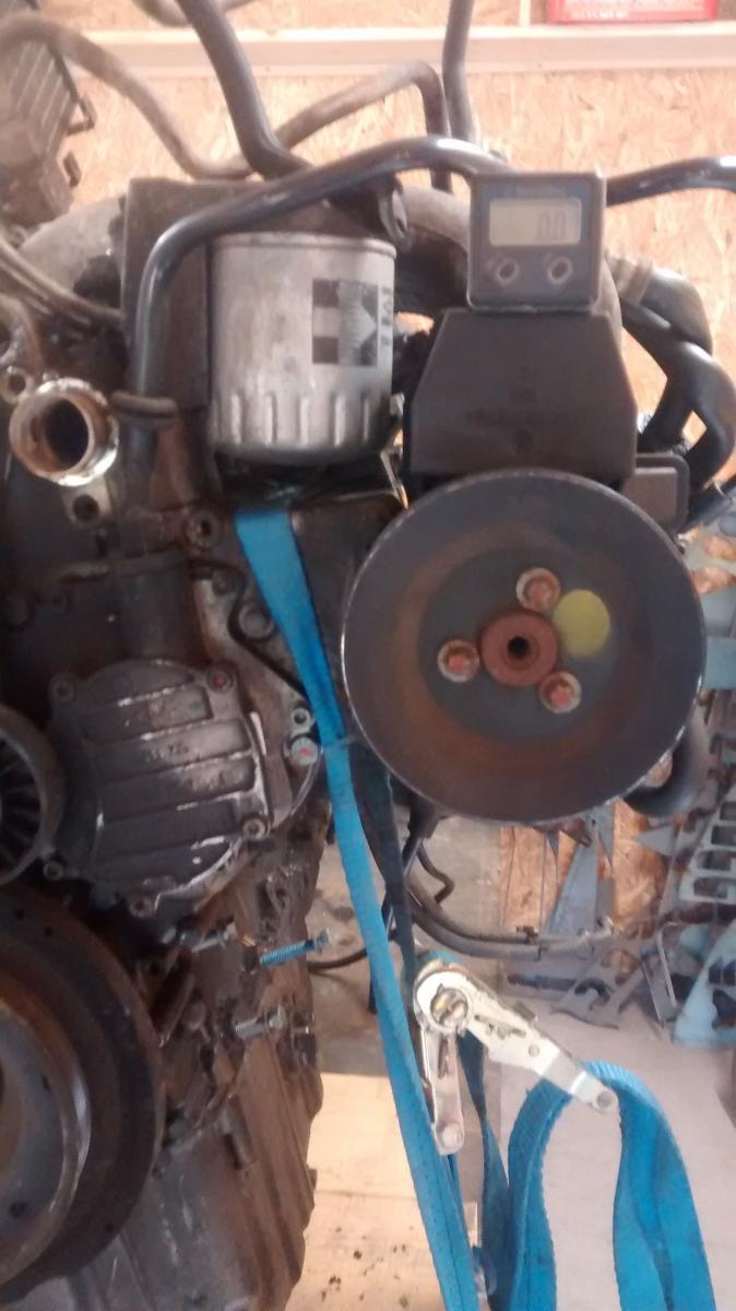
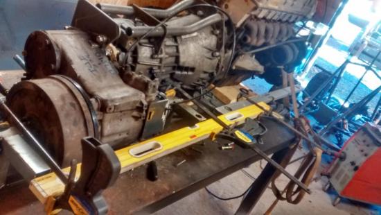
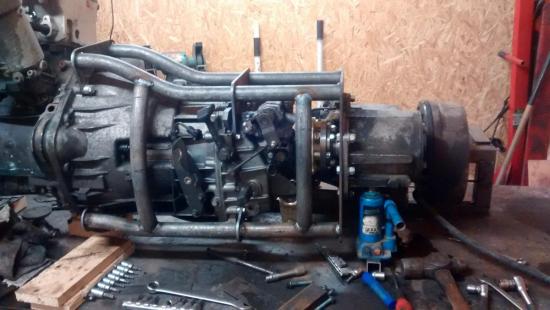
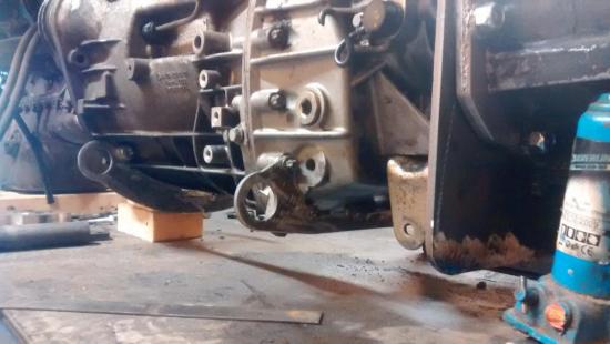
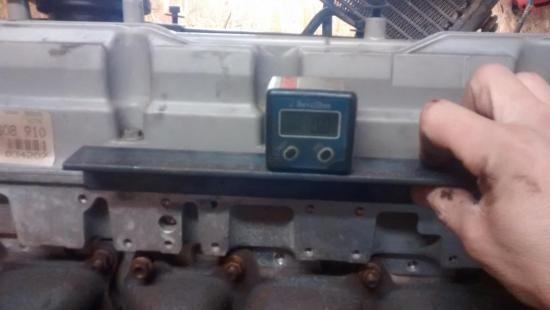
A bit more done. I have taken over three hours making sure everything is straight. The run out on the shaft is 0.015mm which is as good as I can get it. The transfer box is sat totally level with the engine measured with a digital inclinometer. Then I had to make sure that they were inline running in the other plane. The only good reference point is on the engine block where the sump meets the block. I made this very heath robinson jig, and the transfer box is now with 0.5mm of being square this way on. Once I had it like this, I checked the alignment with the flange using feeler gauges between the bolt head and the flange. You measure the same bolt at 90 degree intervals. You can have a maximum of 0.25mm difference and I had just 0.05mm, so quite chuffed with that. Now I know that it is in line. It is a fairly simple job of welding up the tubework which will hold it all together. I want the cradle to be very rigid so that the gearbox and transfer box hang off it. Now I will cut quite a few gussets and plates to add rigidity to it and weld them in. Once I have done this I will take the jig off the transfer box and it should all hang in place. Then I can build the removable cross member and fit it on the bench so that it all sits perfectly level prior to fitting it in the vehicle. This stage has taken far longer than I wanted but it will be worth it down the line.
- 42 svar
-
- 7
-
-
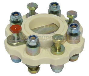
Yes you are right its an R&D coupling. I am very happy with it, it is a very well made thing and you can also check the alignment with feeler guages which I will do prior to welding
-
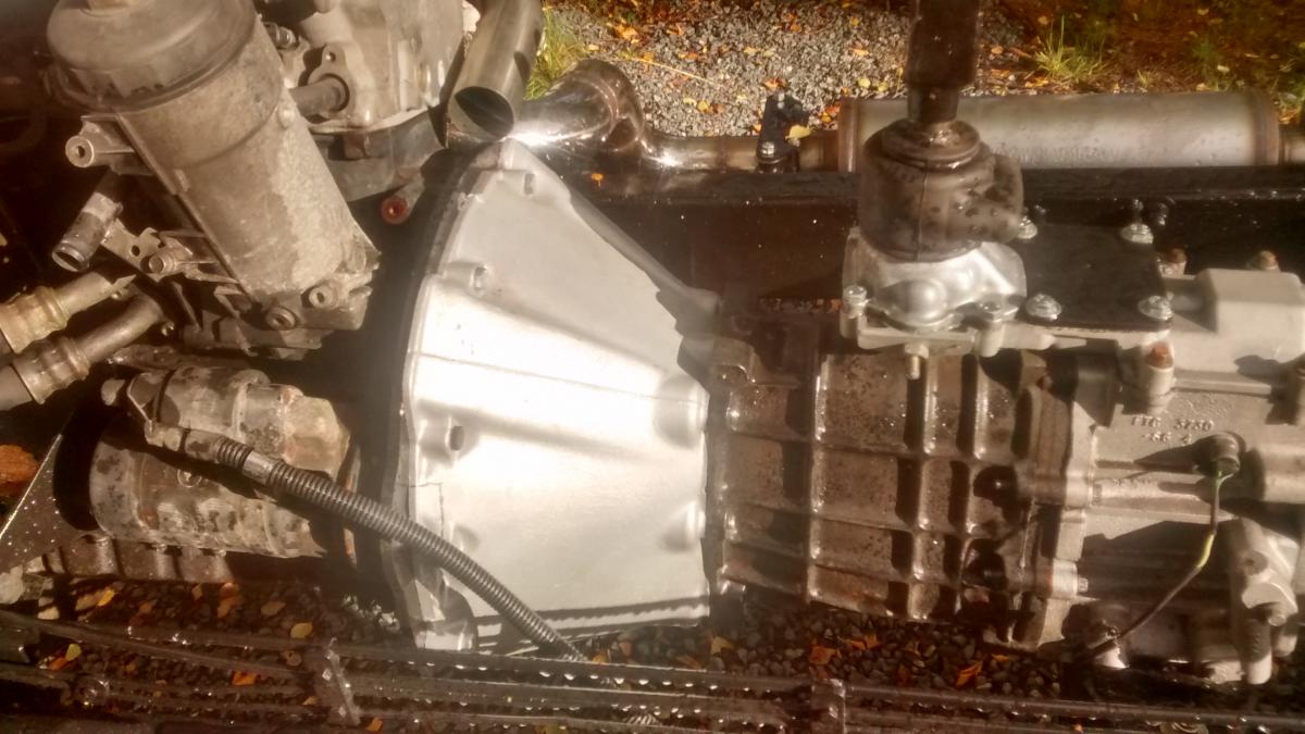
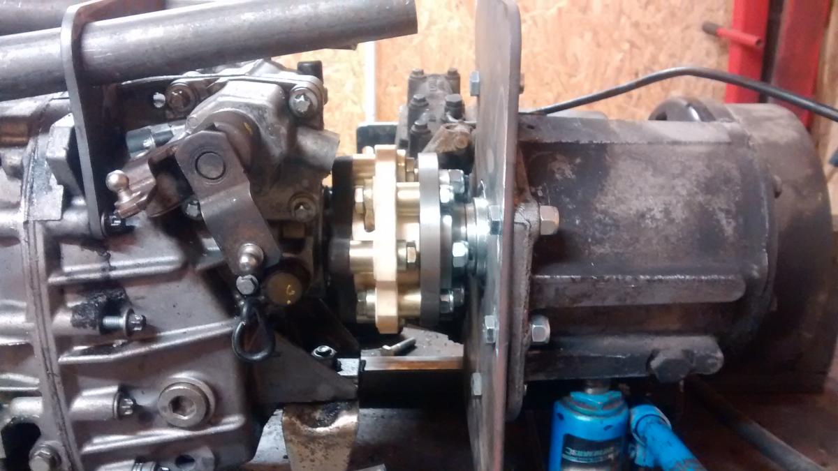
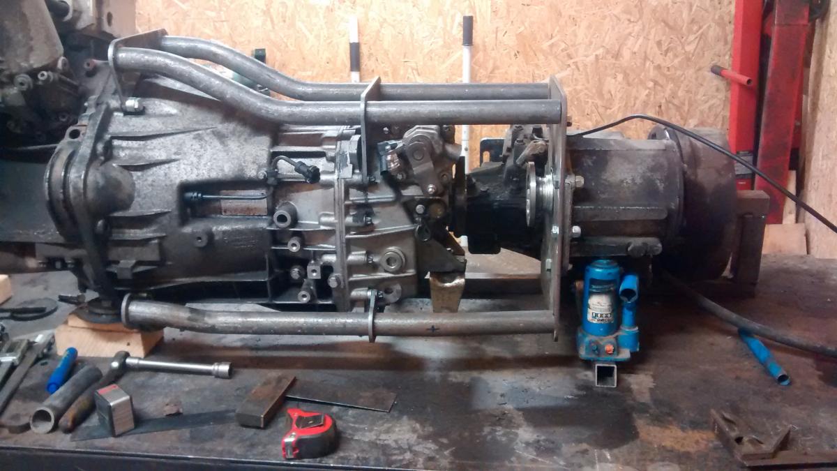
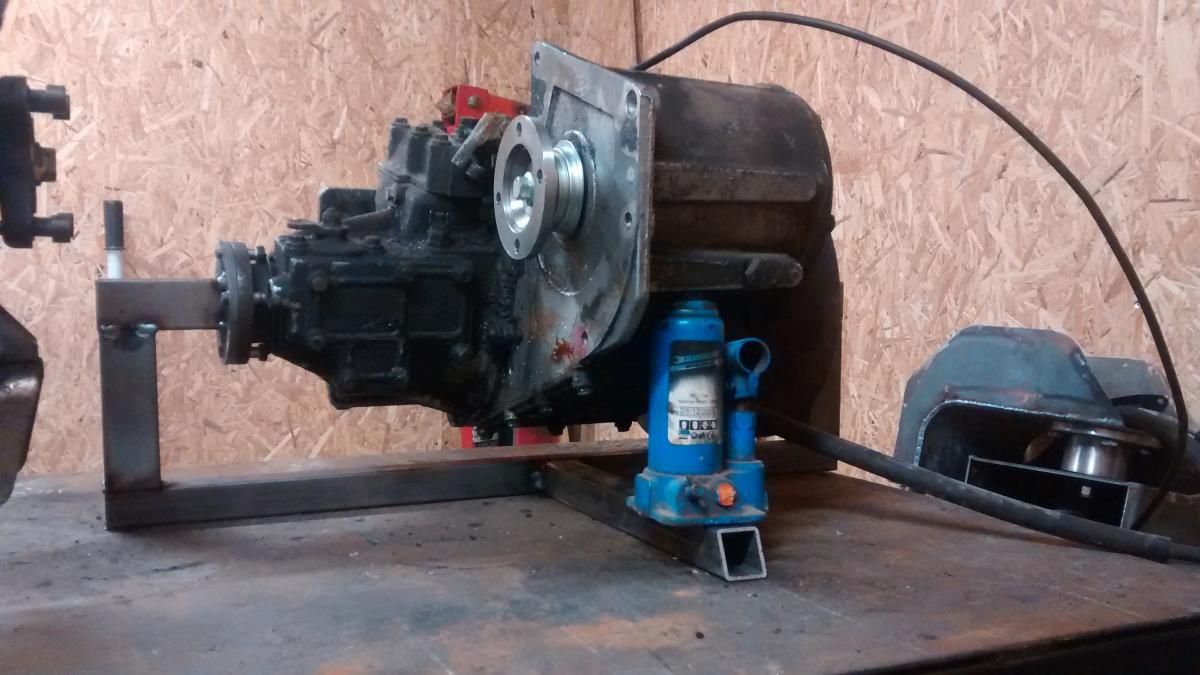
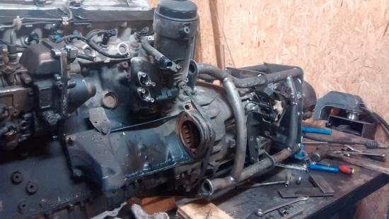
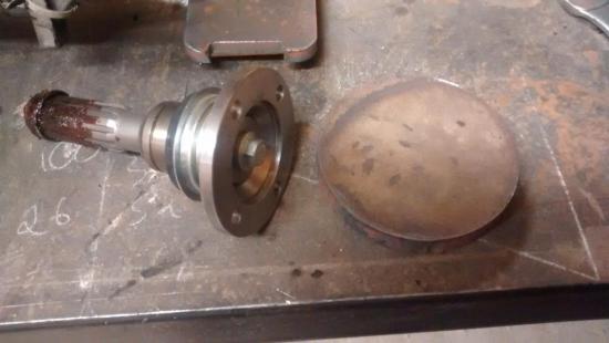
Hello, its been a long while since an update, this is because I was waiting for my coupling. It finally arrive last week, so I have done some work on it today. The coupling bolts straight up to the mercedes gearbox flange, I just had to machine a rebate out of the plastic part. On the other end, there is no way to bolt the coupling up to the input shaft for the transfer box, so I made an adapter to join the two up. This took me ages, mainly because I am not very good at machining, so I have to measure about 1000 times to make sure it is right. I made the adapter ring from scratch and machined the sections out of the input shaft flange so that there is room for all the bolts and nuts. Once I had done this, then I assembled it all and checked the run out with a dial guage. Its not perfect even after taking the whole day making it, but it is very close and well within the tolerances for the coupling. Finally, I slid the transfer box onto the shaft which was very easy, so I can start measuring and trimming the tubes ready for welding. Tomorrow I will build a frame to hold everything perfectly square and then weld the frame up and start re-enforcing it.


- 42 svar
-
- 2
-
-
It is a cheap solution to put the 1.003 gears in the transfer box (In fact its free as I already have a set). I will finish the engine cradle, fit the engine, new tyres, cooling, exhaust, etc... Then I will take the vehicle to Bilprovning and get it passed with the existing gears. Once I have done this I can drive it round a bit and then make the final decision which way to go. I wont order anything until I have done this. I want to leave as many options on the table as possible, so there will be room to fit the overdrive without any modifications. I was just measuring up for various things tonight, and I think that I will move the existing cross member back about 300mm which will also take it upwards also. This will be permanently welded in. Then I will have a removable crossmember to support the gearbox. I think that this will work well
- 42 svar
-
- 1
-
-
No, the GKN ones were quite troublesome. I am going for this one http://roamerdrive.com/ds_overdrive.html . Feedback is pretty good for this unit. I will install the replacement bottom cover with the cooling fins also
- 42 svar
-
- 1
-
-
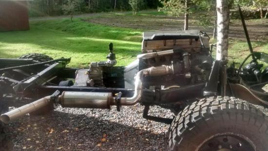
With the overdrive, I hear what you are saying, but I also think it will be OK. I will use the overdrive like 6th gear ie. when I am cruising along steadily to keep the RPM's down. I think that the OM606 will have plenty of power to pull the higher gear, and I have plenty of gears to change down to as soon as the road gets steeper. I envisage that when this happens, I will change down in the overdrive first, and then go down the mercedes gearbox like normal. I want to use 315/75 16 tyres as they are priced reasonably and you can get a tyre which will be pretty nice for longer distance driving. With this tyre, you need more than 0.79 fifth gear and 1:1 in the transfer box - You would be revving at 3350rpm at 100 kmh. With the overdrive on the landrover transfer case, you will be revving at 2800rpm at 100kmh, but more importantly 2540 at 90kmh which is the cruising speed I am aiming for. I think that the engine will pull nicely in this rev range and should have plenty in reserve. The other option is to change out the ring and pinons in the axle for 5.99 ratio and then just have the 0.79 fifth gear. I was originally going to do this, but if one were to break down the line, who knows if I can get spares. Ultimately I can still do this down the line. I can get a 1:1 gearset for the landrover transfer box and sell the overdrive. One thing is for sure, we are going to find out ! I think I am going to take out the crossmember altogether and replace it with a bolt in crossmember which also supports the transfer box like on a landrover. Then there should be room for everything. This will get decided in the next week or so when I take the cab off The pipe was bent by hand in a simple old fashioned push type pipe bender. It took a few adjustments until they were right !
- 42 svar
-
- 2
-
-
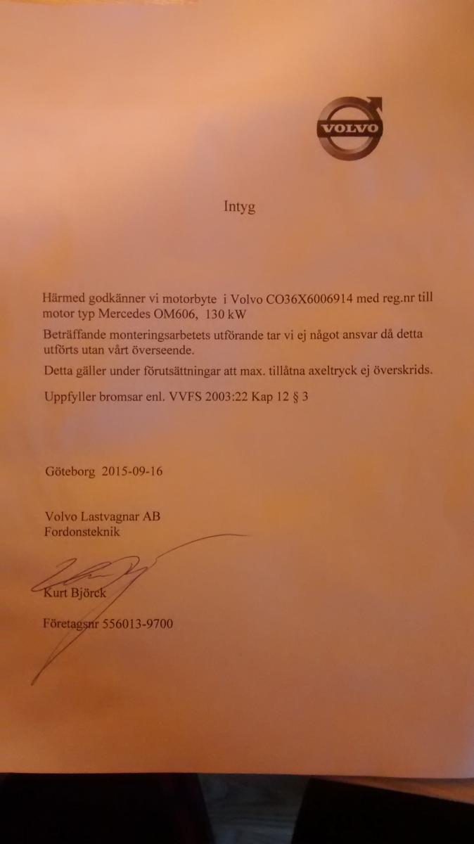
The email address I used was kurt.bjorck@volvo.com I dont think that the sprinter gearbox came with a flex disc. It certainly has a different PCD to any of the mercedes ones I can find. This coupling I have bought will work great I think. I will also have to shorten prop shafts a little also. I wanted the discovery transfer box because it has the correct propshaft offset, it has a transmission handbrake, it is pretty robust and reliable and parts are super cheap. Mainly though, you can get an overdrive which fits straight in. If I keep the existing ratio (1.2:1) then with the overdrive I will have a transfer box ratio of 0.845:1. Coupled with the 0.79:1 in the sprinter gearbox, this means that I can cruise at very low RPMs giving me a quieter and more economical driving experience. Time will tell if I am right !
-
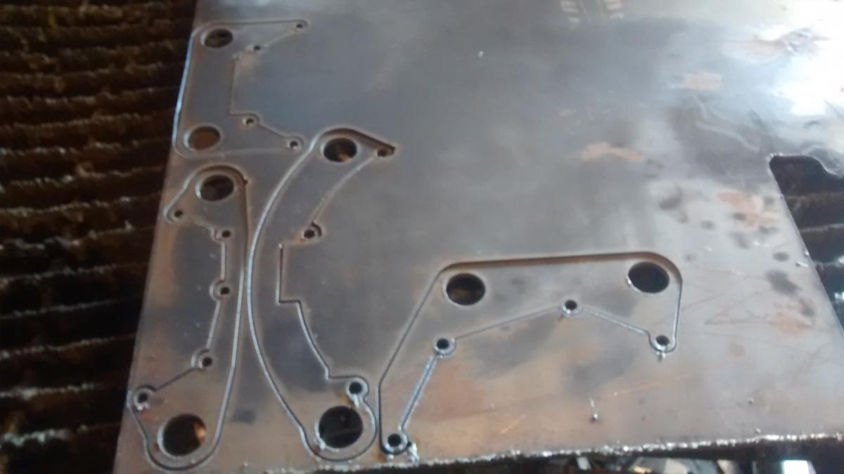
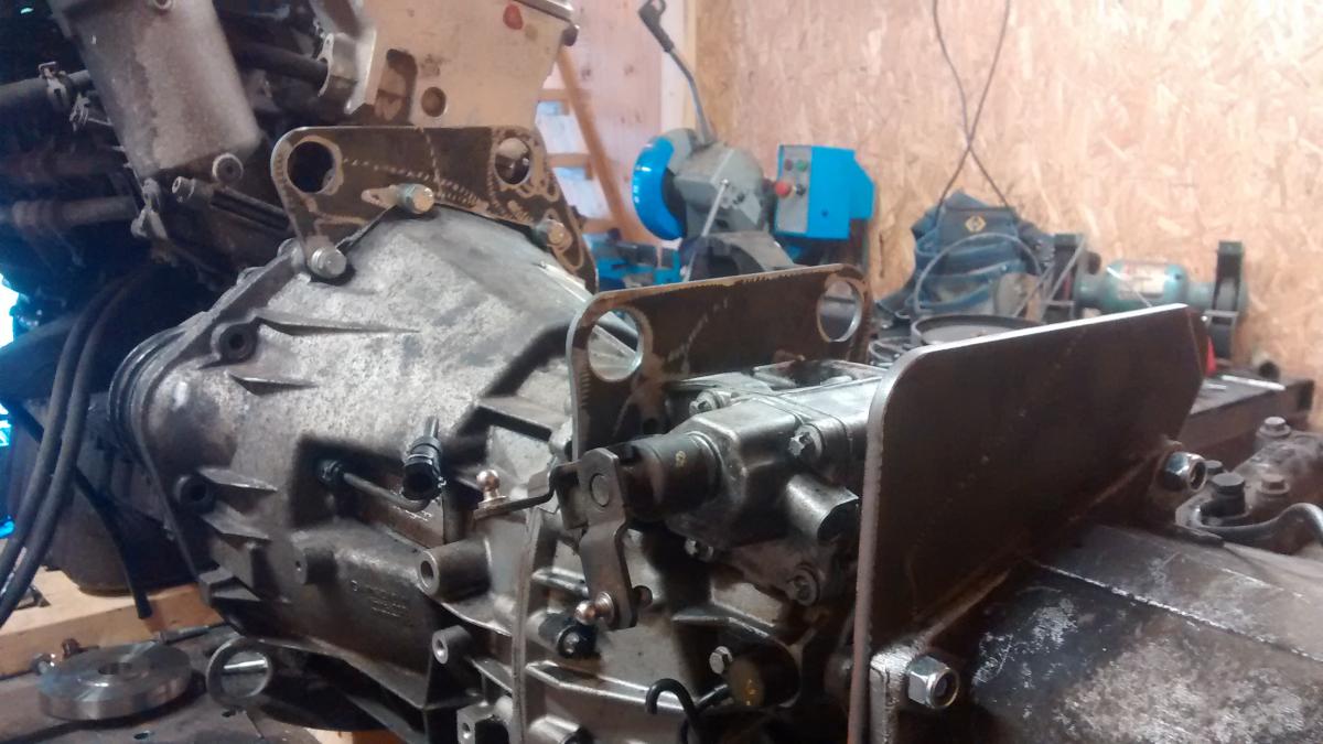
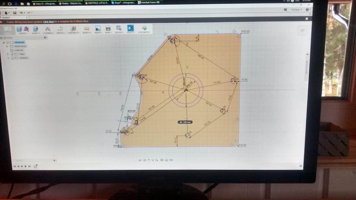
I have been talking to a couple of friends in England who are really good engineers, and they both said that I should have a flexible coupling in between the gearbox and the transfer box. Having looked around, I found this coupling which is designed for boats. It is rated to double the torque output of my motor, and fits the output flange of the mercedes gearbox. Just means I have to make a flange for the input shaft for the transfer box and it should be good to go. I have ordered the coupling and it should come in about 1 week. So now I have decided this, today I thought that I should start to build the cradle which joins the gearbox and transfer case. First I took some measurements and than drew the parts on the CAD system. Then cut them out and cleaned them up. I have to be honest, I am not that great at some of this measuring work, so I cut them in 2mm plate first, and then offer them up, so I can measure how far out I am ! Then I can redraw them and cut them in the 6mm material. This time, 2 out of 4 were right first time, and the other 2 needed some small changes. I would rather waste a bit of 2mm plate than a bit of 6mm plate ! I also took more measurements and made a new mounting plate for the transfer box. This is larger so that it will link up better with the plates which are mounted to the gearbox Next, the plates which I cut earlier were fitted to the gearbox. There are two on the top and two on the bottom. The plan now is to link the plates together with tubes. I am using 34mm outside diameter with 3mm wall thickness. There will be a lot of gussets and strengthening plates and I think that when it is finished it will be very strong. I will use the transfer box mounts from the original TGB gearbox and attach them to this frame. At the moment the gap between the gearbox and transfer box is quite large because I dont know how big the flexible coupler is yet. Once I have fitted this, I will be able to trim these tubes and weld it together. I also have 1 more tube to bend. I cant do much more on this until the coupling comes, so I might make a new intake manifold next. This one is too wide to fit, so I need to make a new one. I dont have the equipment to weld aluminium anymore, so I need to find someone who will weld it for me. Any offers ? My friend is coming with the crane this week, so we will take off the cab and back body and maybe pull out the old engine.


- 42 svar
-
- 10
-
-
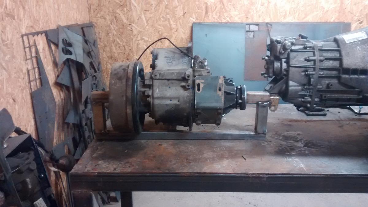
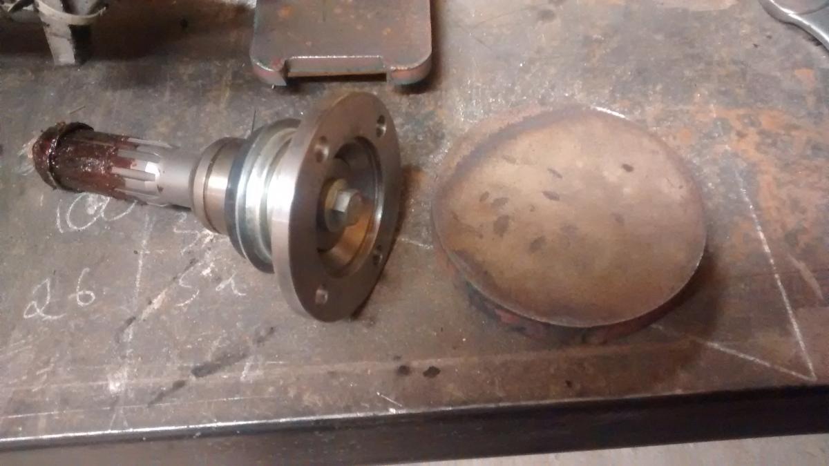
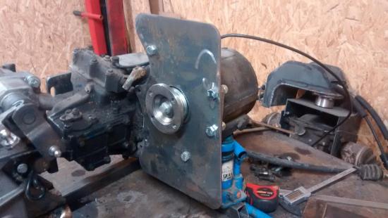
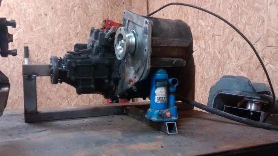
Got a bit more done today. Not very exciting, but the engine, gearbox and transfer box have to be setup perfectly level and at the right height. Started by getting the engine perfectly level in both directions Then I installed the flywheel, clutch and gearbox on the back of the engine Next I built a simple little jig out of some scrap metal. This holds the output shafts of the transfer box so that they are perfectly level. The whole box pivots on these flanges and I have used a little bottle jack so that I can adjust the height of the input shaft to suit the mercedes gearbox output. Now I have everything in line and level. I have made a start machining the adaptor to connect the gearbox and the transfer box. Should get this made tomorrow and then I can start work on the cradle to hold it all together.


- 42 svar
-
- 6
-
-
Thanks Gripen, Am I correct if I assume that if I leave the brakes as standard, that they will meet these demands ?
- 42 svar
-
- 1
-
-
No probs, I will keep all the drawings. I wouldnt want anyone else to have the parts until I have tested my conversion and I am happy that it works with no issues. Once I am happy, I am happy to cut some more parts out
- 42 svar
-
- 2
-
-
Oh, and I also wrote to Kurt at Volvo Trucks and he sent me the letter for Transportstyrelsen. Very helpful and good service. Can anyone tell me what the last sentence means ? I presume it is related to the brakes.

-
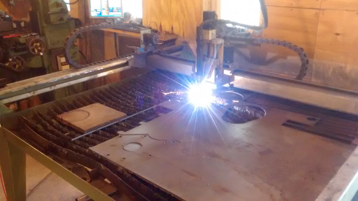
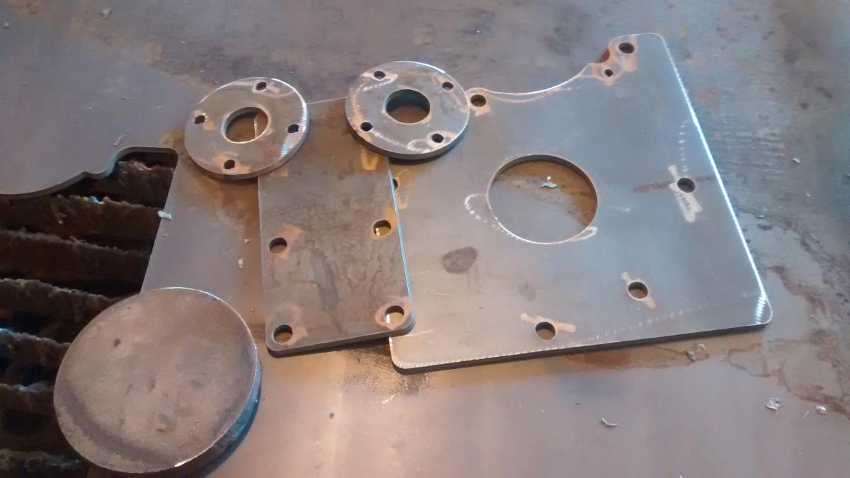
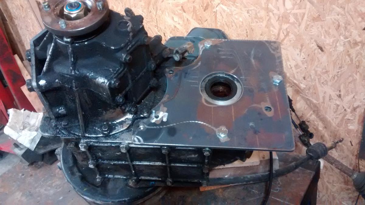
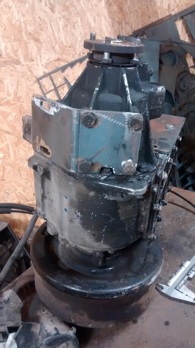
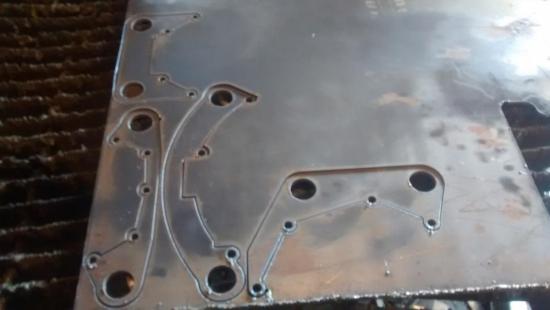
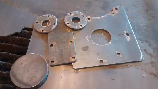
Made a start today with the project. Started off making some parts to mount the transfer box to the cradle I am going to build. I am lucky that I have my own CNC plasma table at home which makes jobs like this much easier. Started off drawing it on the computer Then cut it out on the plasma table Parts ready to go Here they are trial fitted to the transfer box. They are not perfect, but they are fine for what I want to do. Plan now is to get the engine and gearbox sat perfectly level in both directions, then make a frame which holds the transfer box perfectly level and the input shaft at the right height. I also have an input shaft for the LT230 transfer box and I cut out a piece of 20mm plate so that I can make an adaptor to solid mount this to the back of the mercedes gearbox. Things will go a bit slow whilst I get a lot of this setup work done, but I am a bit paranoid to get it perfect. Once it is all exactly right, then the cradle should be made quite quickly. Just need to find out the torque settings for the flywheel to crankshaft bolts on an OM606. If anyone knows, please let me know !


- 42 svar
-
- 4
-